Lab 3: ToF
Lab 3: Time of Flight Sensors
Prelab
I2C Address
The VL53L1X ToF sensor has a default I2C address of 0x52 (which shows up as 0x29 in the 7-bit format since the Arduino I2C scanner drops the R/W bit). Both sensors ship with this same address, so we can’t talk to them independently without changing one.
Using Two ToF Sensors
Since both sensors share the same I2C address, I’m using the XSHUT pin to change one sensor’s address at boot. Here’s the approach:
- Wire the XSHUT pin of one sensor to a GPIO on the Artemis
- At startup, hold that sensor in shutdown (pull XSHUT low)
- Change the address of the other sensor using
setI2CAddress() - Bring the second sensor back up, which will have the default address
- Now they have different addresses and can be read independently
ToF sensor 2 online at address 0x54!
ToF sensor 1 online at address 0x29!
Wiring
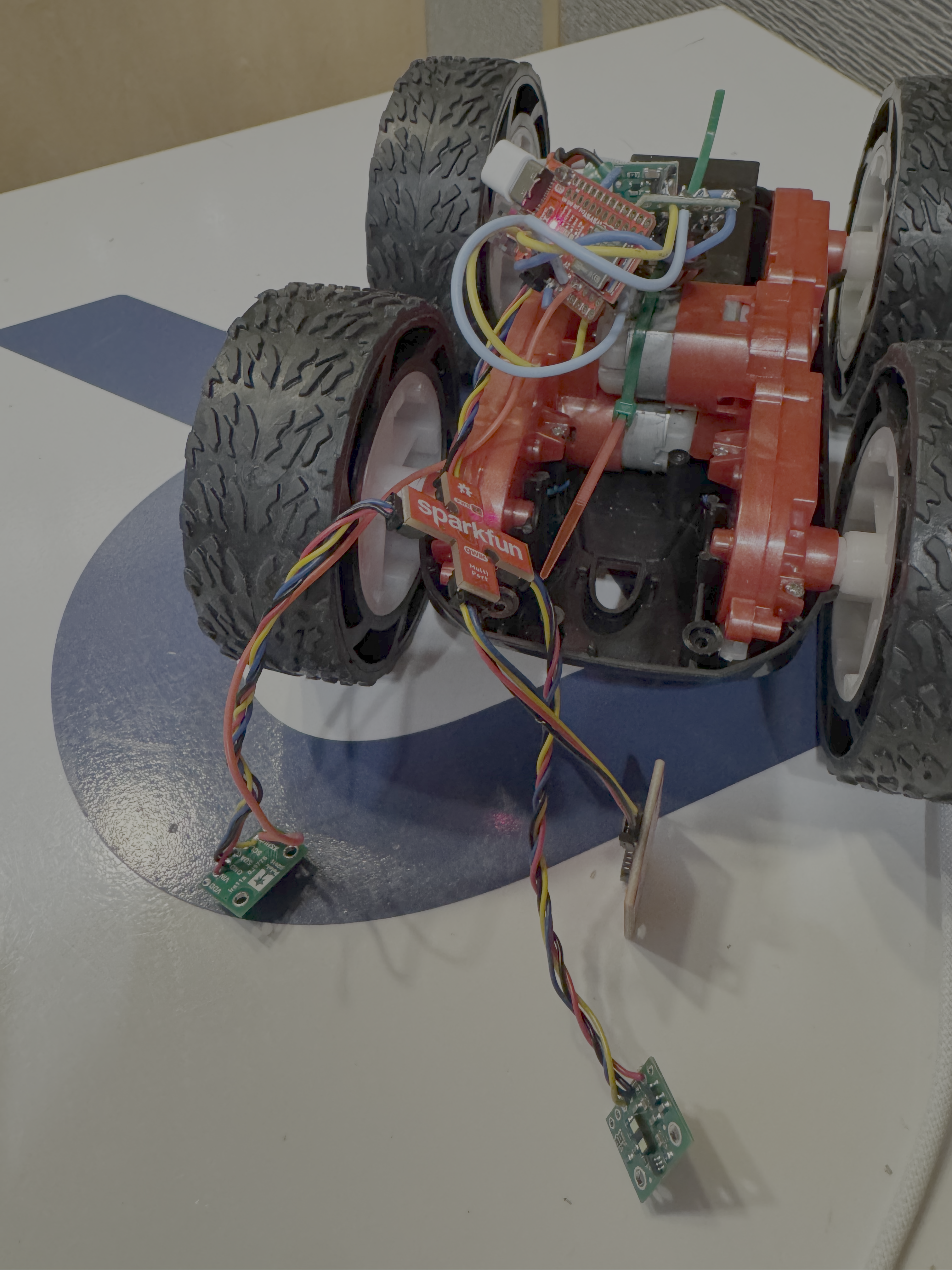
The Artemis connects to the QWIIC breakout board, which acts as a splitter, and both ToF sensors and the IMU all share the same I2C bus through it. Each sensor has a QWIIC cable soldered on.
The XSHUT pin on one ToF sensor is wired to a GPIO on the Artemis so we can hold it in shutdown during boot and reassign the other sensor’s address.
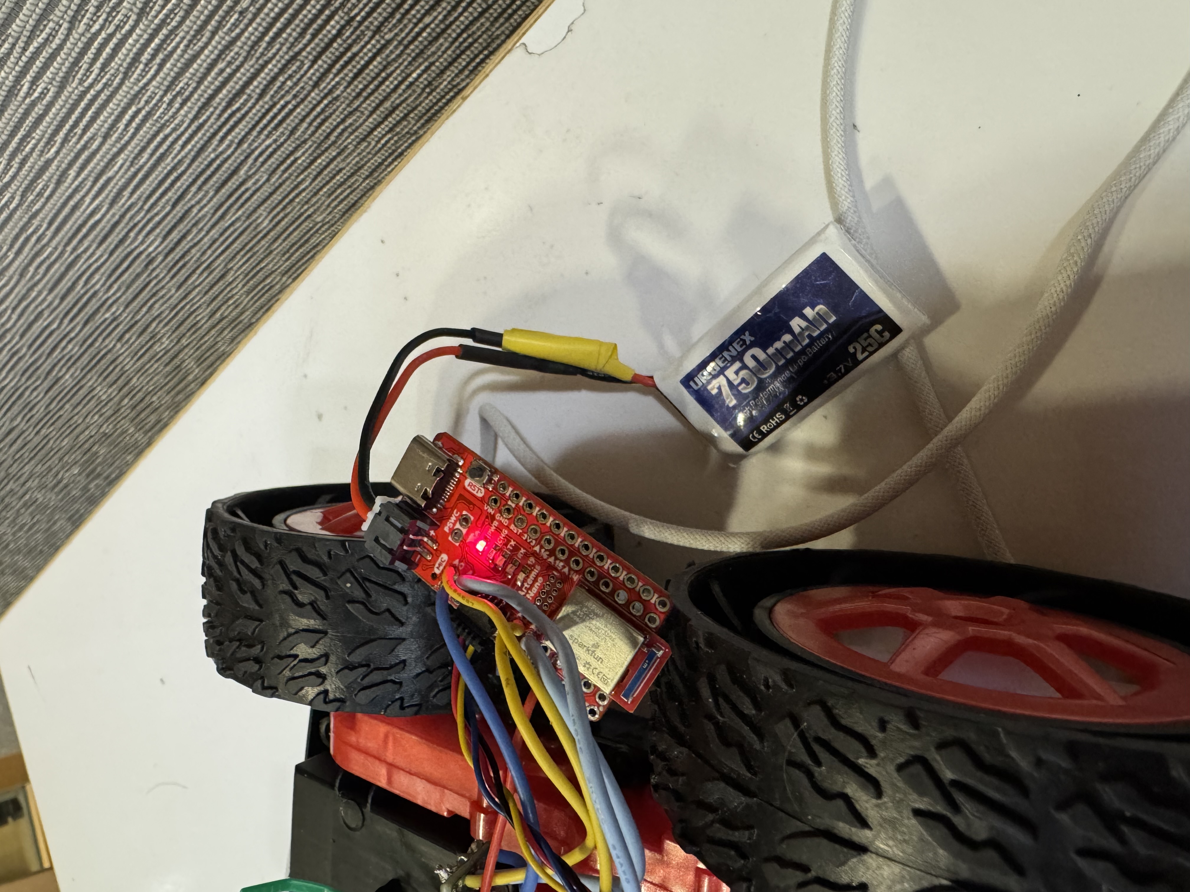
Battery & Artemis Power
I soldered a JST connector to the 750mAh battery. Key things:
- Cut battery wires one at a time
- cutting both simultaneously shorts the terminals and kills the battery
- Used heat shrink to insulate the solder joints.
- Double-checked polarity before plugging in — positive on the battery to positive on the Artemis
ToF Sensor Setup
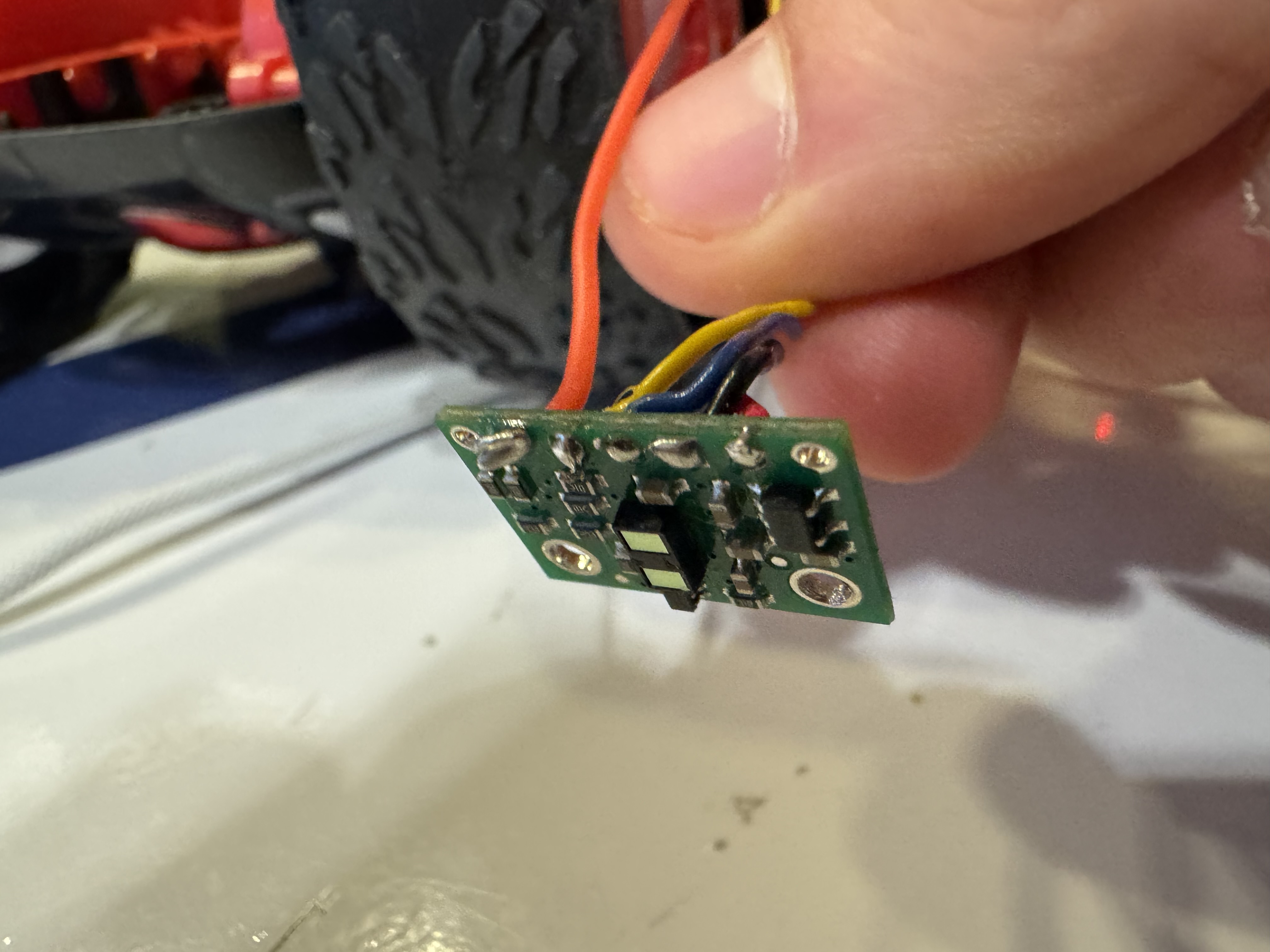
Hardware Connection
I connected the first ToF sensor to the QWIIC breakout board using a QWIIC cable — cut one end and soldered it to the sensor pads. The wire colors are:
- Black -> GND
- Red -> 3.3V
- Blue -> SDA
- Yellow -> SCL
Ranging Mode Selection
The VL53L1X has three distance modes:
- Short (1.3m) — faster ranging and better ambient light immunity, but very limited range
- Long (4m, default) — max range, but slower and more affected by ambient light
ToF Sensor Characterization
I updated my BLE code from lab 2 and added the ability to read the ToF sensor. I collected samples over BLE through a Jupyter notebook, then computed the mean, std deviation, and error for each measurement.
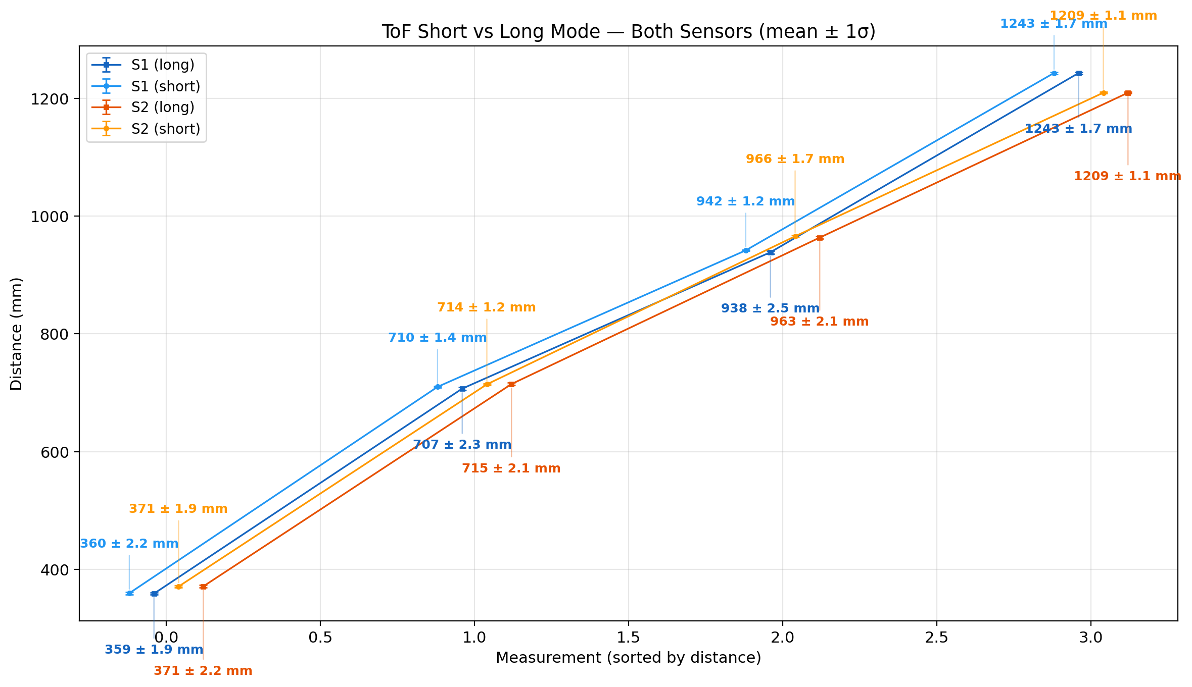
From these tests, I learned that both sensors are fairly accurate at a range of distances, I did not notice a a huge difference in accuracy, but it was faster to measure in short mode.
Two ToF Sensors
After wiring both sensors to the QWIIC breakout board (with XSHUT on one), the startup code changes one address so both can run simultaneously.
The firmware uses distanceSensor.checkForDataReady() to read each sensor non-blockingly, pushing timestamped readings into circular buffers:
void read_tof() {
  if (distanceSensor1.checkForDataReady()) {
    const int time = micros();
    int distance = distanceSensor1.getDistance();
    distanceSensor1.clearInterrupt();
    tof1_times.push(time);
    tof1_dist.push(distance);
  }

  if (distanceSensor2.checkForDataReady()) {
    const int time = micros();
    int distance = distanceSensor2.getDistance();
    distanceSensor2.clearInterrupt();
    tof2_times.push(time);
    tof2_dist.push(distance);
  }
}
ToF Sensor Speed
The main loop uses checkForDataReady() to poll each sensor without blocking, so the loop itself runs much faster than the sensors can produce readings.
ToF1: 255 samples, 9.7 samples/sec (26.09s window)
ToF2: 255 samples, 10.0 samples/sec (25.42s window)
Throughput is about 10 samples per second.
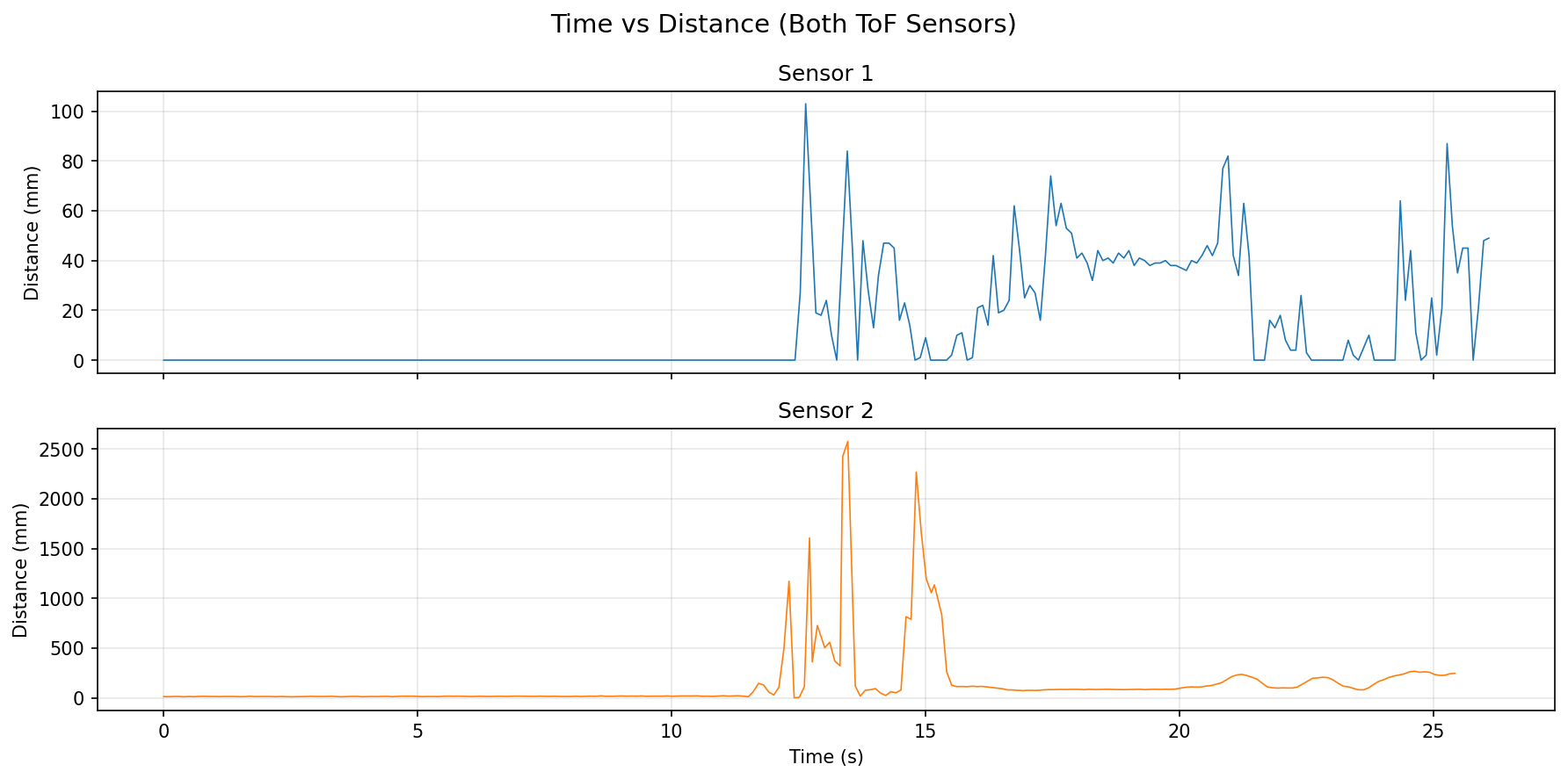
Time vs Distance
I recorded timestamped ToF data from both sensors over BLE and plotted distance vs time.
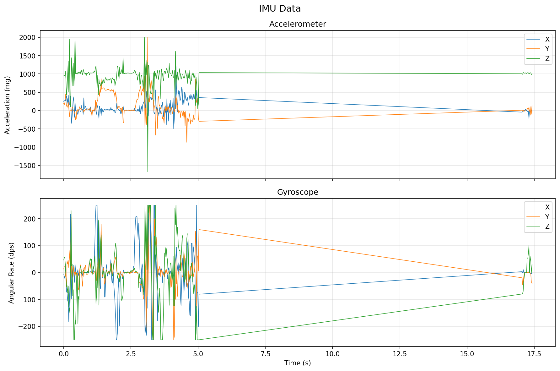
IMU vs Distance
I also recorded and timestamped the IMU data and plotted it against time.